Parts of a Motherboard and Their Functions
By Marlo Strydom · Last updated
Learning your way around a motherboard makes it much easier to build, upgrade, or troubleshoot a computer. Once you know what each socket, slot, port, and header does, the board stops looking like a maze of parts.
A motherboard is the main circuit board that carries data and power between a computer's components and determines which hardware the system supports. This guide shows how the motherboard connects the main parts of a computer, where its key components sit, and why each one matters.
Main Parts at a Glance
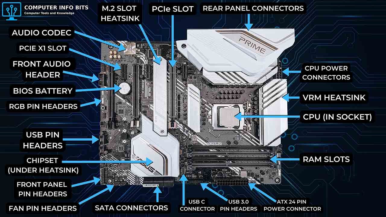
Ports, Slots, Sockets, and Headers
A motherboard connection may be called a socket, slot, port, header, or connector. These words are related, but they do not mean the same thing. The table below shows how each term is normally used.
| Term | What It Means | Common Examples |
|---|---|---|
| Socket | A fitted connection that holds a component in a set position | CPU socket and M.2 socket |
| Slot | A long or flat connection that accepts a card or memory module | DIMM slot and PCIe slot |
| Port | A connection used by a cable or external device | USB, Ethernet, audio, and SATA ports |
| Header | A small group of pins for an internal cable | Fan, USB, audio, and front panel headers |
| Connector | A broad name for an electrical connection on the board | 24-pin ATX power connector |
Manufacturers sometimes use these words in slightly different ways. The labels printed on the board and the motherboard manual give the correct name for each connection on a specific model. To find your model without opening the case, our free PC Reporter names the board in Windows.
CPU Socket
The CPU socket is the large connector that holds the processor on the motherboard. It provides the physical mount and the electrical contacts that meet the pads under the processor, letting the CPU communicate with the rest of the system. When people talk about motherboard compatibility, the socket is one of the first things they mean.
Each socket supports a limited group of processors. Many current desktop platforms use LGA, which places the contact pins in the motherboard socket. AMD Socket AM5 also uses an LGA design, while older AMD AM4 processors use PGA. Always match the exact socket and supported CPU list before buying a processor.
Chipset
The chipset helps manage communication between the processor and many motherboard features. Depending on the platform, it can provide extra PCIe lanes, SATA ports, M.2 connections, USB ports, networking, and other input and output functions.
Older motherboards split this work between the northbridge and southbridge. The northbridge handled faster links to the CPU, RAM, and graphics interface. The southbridge handled slower features such as USB, audio, and storage. Modern desktop platforms have moved many northbridge jobs into the CPU and use one main chipset for extra connections.
The chipset is why two boards with the same CPU socket can offer different numbers of USB ports, SATA ports, M.2 slots, and PCIe connections. The socket tells you which processor can fit, while the chipset helps define the rest of the board's features.
RAM and Memory Slots
The memory slots, also called RAM slots or DIMM slots, hold the memory modules used by the system. These slots connect RAM to the motherboard so the processor can reach active data quickly.
Desktop motherboards use DDR memory. DDR4 and DDR5 modules may look similar, but they are not interchangeable. The notch and electrical design are different, so a DDR5 module will not fit a DDR4 slot, and a DDR4 module will not fit a DDR5 slot.
Many consumer motherboards have two or four memory slots. Installing a matched pair in the recommended DIMM slots normally enables dual-channel operation. The motherboard manual shows which slots to fill first, and a RAM calculator can help plan the layout. Once the modules are in, our free RAM Optimizer checks that they run in dual channel at their rated speed.
Expansion Slots and Slot Types
Expansion slots let the motherboard accept add-in cards. The current standard is PCI Express, usually shortened to PCIe. A PCIe slot can hold a graphics card, network card, sound card, USB card, storage controller, capture card, or another supported device.
PCIe connections are described by their lane count. The main types found on desktop motherboards are:
- PCIe x16: Uses up to 16 lanes and is normally used for a graphics card
- PCIe x8: Uses up to eight lanes and is common for storage, networking, and secondary expansion cards
- PCIe x4: Uses up to four lanes and can support capture cards, storage adapters, and fast network cards
- PCIe x1: Uses one lane and is common for sound cards, USB cards, and smaller add-in cards
- PCI: A legacy slot used by older sound cards, modems, network cards, and storage controllers
- AGP: An older graphics-only slot that was replaced by PCIe
The x1, x4, x8, and x16 labels show how many data lanes the connection can use. Physical slot length does not always reveal the wired lane count. A full-length slot may run at x16, x8, or x4, so check the motherboard manual when lane speed matters.
PCI and AGP may still appear in older computers, but most current consumer motherboards use PCIe for add-in cards.
Storage Connectors
Storage connectors let the system communicate with hard drives, solid-state drives, and optical drives. The two main types on desktop motherboards are SATA ports and M.2 sockets.
SATA Ports
SATA ports connect hard drives, SATA SSDs, and optical drives to the motherboard. Each drive uses a data cable to the board and a separate power cable from the power supply. SATA replaced older IDE and PATA connections, which used wide ribbon cables.
M.2 Socket and NVMe
An M.2 socket lets a small SSD plug directly into the motherboard. Many M.2 sockets support NVMe, which can use PCIe lanes for much higher storage performance than SATA. Use the storage speed comparison tool to compare the practical differences between drive types.
Not every M.2 socket supports the same drive type or speed. Some boards also share connections between an M.2 socket and a SATA port. In those layouts, installing one drive can disable a shared SATA port.
Important: Before filling every M.2 socket and SATA port, check the storage table or block diagram in the motherboard manual. It shows supported drive types and any connections that share bandwidth.
Power Connectors and VRM
The motherboard receives power through its main 24-pin ATX power connector and one or more CPU power connectors, often 8-pin. The 24-pin connection supplies the board, while the CPU power connection feeds the processor's power circuit.
Near the CPU socket is the voltage regulator module, usually shortened to VRM. It changes power supply voltage into the lower, steady voltage needed by the CPU and nearby parts. A VRM normally includes power stages or MOSFETs, chokes, capacitors, and a controller.
VRM heatsinks draw heat away from this power circuit. Their size and design matter more when a processor draws high power for long periods.
BIOS Chip and CMOS Battery
The BIOS chip stores the motherboard firmware used when the system starts. Most current boards use UEFI, but many people still call it BIOS. The firmware checks the hardware, prepares boot devices, and starts loading the operating system.
The CMOS battery, also called the BIOS battery, keeps the real-time clock running and helps retain firmware settings while the computer is unplugged. A weak battery can cause the clock to reset or saved settings to return to their defaults.
Clearing the CMOS resets saved firmware settings. Depending on the board, this may use a jumper, a button, or another method listed in the motherboard manual.
Back Panel Ports and What They Do
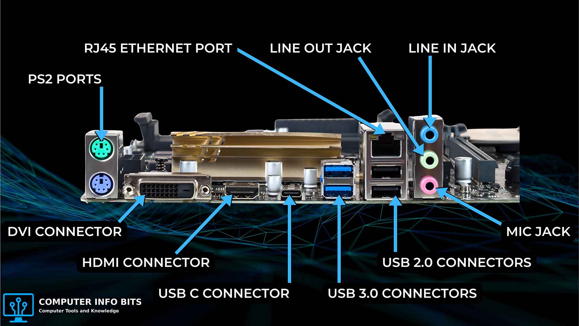
The rear I/O panel is the group of motherboard ports at the back of the computer. These connections let external devices communicate with the board. The exact layout depends on the model, so the manufacturer's port guide or motherboard manual can help identify an unfamiliar connector.
- USB ports: Connect keyboards, mice, storage devices, printers, and other peripherals
- Ethernet port: Connects the computer to a wired network through an RJ-45 cable
- Audio jacks: Connect speakers, headphones, microphones, and line-level audio equipment
- Display outputs: Connect a monitor when the processor and motherboard support onboard display output
- Wi-Fi antenna connectors: Attach external antennas on boards with built-in wireless networking
- PS/2 port: Connects a compatible legacy keyboard or mouse
I/O Shield
The I/O shield is the thin plate fitted between the motherboard's rear ports and the opening in the computer case. It fills the space around the ports and helps them line up with the case opening. Some motherboards use a separate shield that must be installed first, while others have one built into the rear I/O assembly.
Network and sound hardware is often built into the motherboard. That is why Ethernet and audio ports are normally available without separate network or sound cards.
Front Panel Connectors and Headers
The front panel connectors are small pins that link the computer case buttons and lights to the motherboard. This group is also called the front panel header and is often found along the bottom edge of the board.
- Power switch: Connects the case power button to the board
- Reset switch: Connects the case reset button
- Power LED: Shows whether the system is on or in a power-saving state
- Drive activity LED: Flashes when a storage drive is being accessed
- Speaker pins: Connect an internal speaker that can play POST beep codes
Other Internal Headers
Motherboards can also include fan headers, USB headers, front-panel audio headers, USB-C headers, and RGB or addressable RGB headers. Fan headers power the CPU cooler and case fans so the board can monitor and control system cooling.
If the power switch cable is on the wrong pins, a newly built PC may appear completely dead. The motherboard manual shows the exact pin layout and the correct direction for each LED plug.
Types and Form Factors
Motherboard types are grouped by their form factor. The form factor sets the board's size, mounting-hole pattern, and general layout. The most common desktop sizes are ATX, Micro-ATX, and Mini-ITX.
Form factor affects case fit and the amount of room available for memory slots, PCIe slots, storage connectors, and rear ports. A larger board usually offers more expansion space, while a smaller board fits into a more compact case.
- ATX: A standard desktop size with room for several expansion slots and connectors
- Micro-ATX: A shorter board that normally has fewer expansion slots than ATX
- Mini-ITX: A compact board that normally has two RAM slots and one expansion slot
Once these names make sense, the motherboard manual becomes far easier to use. You can follow its labels and find the exact socket, slot, port, or header you need without guessing.
Related Posts