Parts of a Motherboard and Their Functions
By Marlo Strydom · Last updated
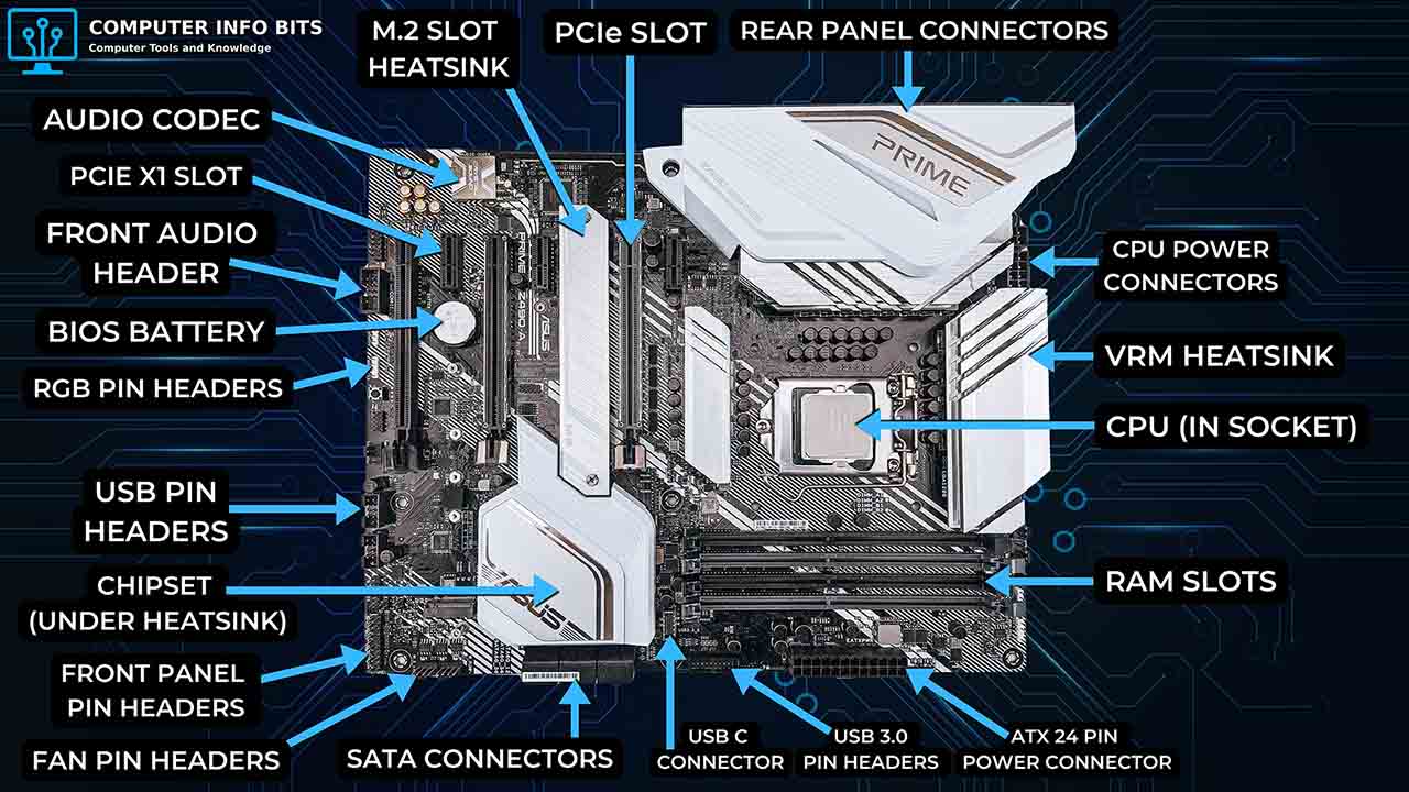
Take the side panel off a desktop PC, and the big board that every other part of a computer plugs into is the motherboard. It looks like a maze of slots and pins at first, but there are only ten main parts to learn, and each one has a single job.
CPU Socket
The CPU socket is the square mount near the top of the board that holds the processor. Its contacts touch the pads under the processor, which carry power in and send data to and from the rest of the PC.
Each socket fits only certain processors, so it's the first thing to check for motherboard compatibility. Intel boards and AMD's AM5 boards use LGA, with the pins in the socket. AMD's older AM4 boards use PGA, with the pins on the processor.
Chipset
The chipset is a support chip that usually sits under a flat heatsink near the bottom of the board. Intel calls it the PCH. It runs the extra USB ports, SATA ports, M.2 slots, and PCIe lanes that the processor doesn't handle on its own.
Older boards split this work between two chips. The northbridge handled fast links to the RAM and graphics card, and the southbridge handled slower devices. The northbridge's jobs have since moved into the CPU, so a modern board needs just one chipset.
That's why two boards with the same socket can offer very different features. The socket decides which CPU fits, and the chipset shapes the rest of the board.
RAM Slots
RAM slots, also called DIMM slots, sit beside the CPU socket and hold the memory sticks. Desktop boards usually have two or four, and our RAM calculator shows how much memory to put in them.
A board takes either DDR4 or DDR5 memory, almost never both. The notch sits in a different spot on each type, so a DDR5 stick won't fit a DDR4 slot, and the reverse is true too.
Two matching sticks in the recommended slots run in dual channel, which gives the CPU more memory bandwidth. Our guide on which RAM slots to use shows the right pair, and our free RAM Optimizer checks that they actually run that way at their rated speed.
PCIe Expansion Slots
Expansion slots hold add-in cards, most often the graphics card. Modern boards use PCI Express (PCIe) slots, named for how many data lanes they use.
- PCIe x16: The longest slot, used for graphics cards
- PCIe x8: Used by some network, storage, and RAID cards
- PCIe x4: Fits capture cards, fast network cards, and M.2 adapter cards
- PCIe x1: The shortest slot, for Wi-Fi, sound, and USB cards
A slot's length doesn't always match its wiring. A full-length slot may only use eight or four lanes, so check the board's specs before adding a second card. Very old boards may also have PCI or AGP slots, which PCIe replaced.
Storage Connectors
SATA Ports
SATA ports connect hard drives, 2.5-inch SSDs, and DVD drives through a thin data cable. Each drive also needs its own power cable from the power supply. SATA replaced the wide IDE ribbon cables on older PCs.
M.2 Slots and NVMe
An M.2 slot holds a small, stick-shaped SSD that screws flat onto the board, often under a heatsink. Most M.2 slots support NVMe drives, which use PCIe lanes and run much faster than SATA drives.
Before you add drives: Some M.2 slots only take certain drive types, and some share lanes with SATA ports. On those boards, filling an M.2 slot can switch off a SATA port, and the manual's storage table shows which ones share.
Power Connectors and VRM
Power comes in from the power supply through the 24-pin ATX connector, which feeds the whole board. One or more CPU power connectors, usually 8-pin, feed the processor.
VRM (Voltage Regulator Module)
The VRM is the group of small parts lined up beside the CPU socket. It turns power from the supply into the steady, low voltage the CPU needs, using power stages (MOSFETs), chokes, and capacitors run by a controller chip.
This circuit gets hot under heavy loads, so it sits under finned heatsinks. A strong VRM matters most for high-power CPUs that run at full power for a long time.
BIOS Chip and CMOS Battery
The BIOS chip stores the firmware that starts the PC. It checks the hardware, finds a boot drive, and then hands control to Windows or another operating system. Modern boards use UEFI firmware, but most people still call it the BIOS.
The CMOS battery is a coin cell that keeps the clock running and saves your BIOS settings while the PC is unplugged. When it runs low, the clock and settings can reset each time the power is cut.
Clearing the CMOS puts every BIOS setting back to default, which can fix a PC that won't boot after a bad setting change. Boards do it with a jumper, a button, or by taking the battery out for a short time.
Back Panel Ports and What They Do
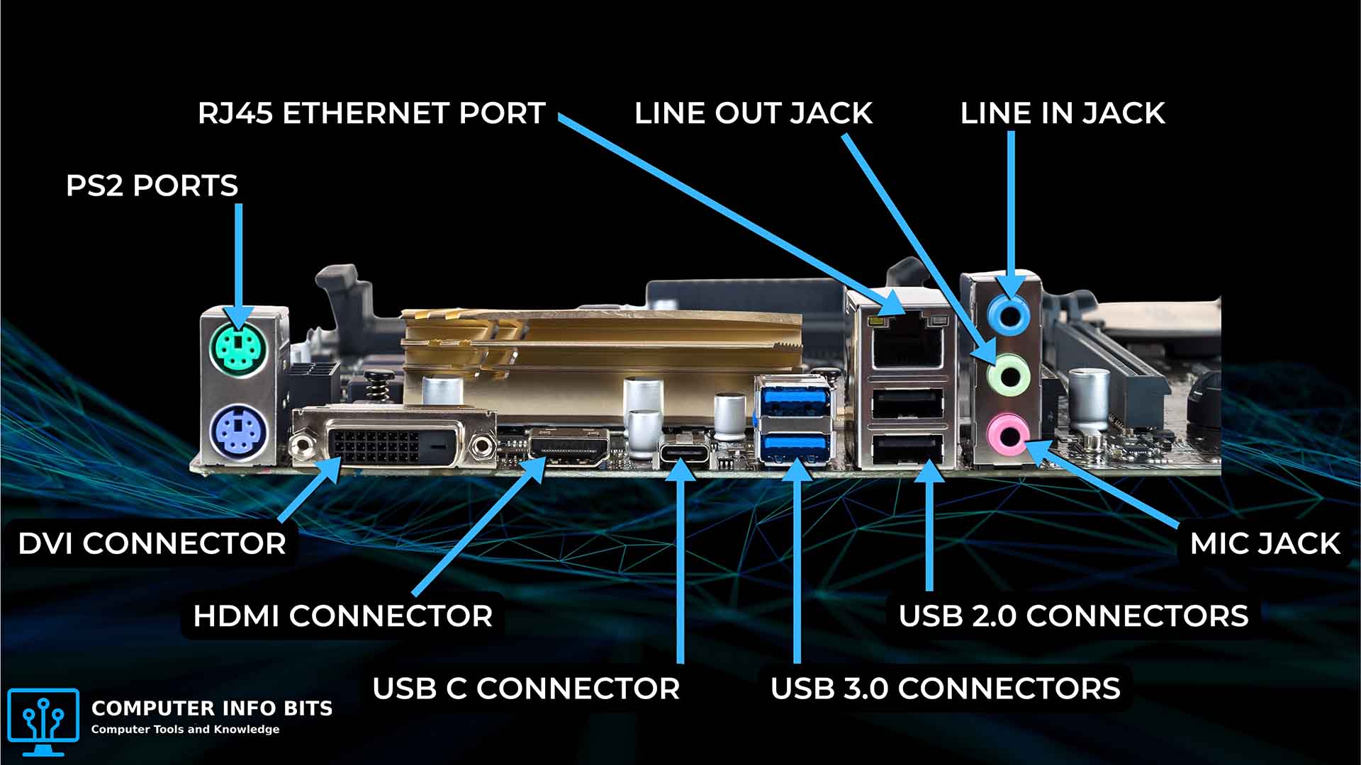
The rear I/O panel is the row of motherboard ports on the back of the PC. Every model's layout is a little different, and this port guide with photos helps you name an unfamiliar plug.
- USB-A and USB-C ports: Connect keyboards, mice, drives, phones, and printers
- Ethernet port: Connects to your router with a wired RJ-45 network cable
- Audio jacks: Connect speakers, headphones, and microphones
- HDMI and DisplayPort: Connect a monitor when the CPU has built-in graphics. With a graphics card, plug into the card instead
- Wi-Fi antenna connectors: Hold the antennas on boards with built-in Wi-Fi
- PS/2 port: Connects an older keyboard or mouse
The Ethernet and audio jacks work without extra cards because a network chip and an audio codec chip are built into the board.
I/O Shield
The I/O shield is the thin metal plate that frames the rear ports in the case opening. Some boards have it built in, while others ship it loose, and a loose shield must snap into the case before the board goes in.
Front Panel Connectors and Headers
The front panel header is a small block of pins, usually on the bottom edge of the board, that links the case's buttons and lights.
- Power switch: Connects the case power button
- Reset switch: Connects the case reset button
- Power LED: Lights up while the PC is on
- Drive activity LED: Flashes when a drive is busy
- Speaker: Beeps POST codes that point to startup errors
If the power switch plug is on the wrong pins, a new build looks completely dead. The manual's pin map shows where each plug goes, and LED plugs only light up when they face the right way.
Other Internal Headers
More headers connect the case's front USB and USB-C ports, front audio jacks, and RGB lighting. Fan headers power the CPU cooler and case fans, and the board speeds them up or slows them down to manage system cooling.
Ports, Slots, Sockets, and Headers
Manuals and board labels use these five words for different kinds of connections.
| Term | What It Means | Examples |
|---|---|---|
| Socket | Holds a part in one fixed spot | CPU socket |
| Slot | A long opening that a card or memory stick pushes into | PCIe and DIMM slots |
| Port | Takes a cable or an outside device | USB, Ethernet, and SATA ports |
| Header | A small group of pins for an internal cable | Fan, USB, and front panel headers |
| Connector | Any electrical plug on the board | 24-pin ATX power connector |
To find the right manual, you need the board's exact model name. It's printed on the board, or our free PC Reporter shows it in Windows without opening the case.
Types and Form Factors
Motherboards come in standard sizes called form factors. The form factor sets the board's size and screw-hole layout, which decides which cases it fits. The common sizes are:
- ATX (12 x 9.6 in): The standard size, with room for several PCIe slots
- Micro-ATX (9.6 x 9.6 in): A shorter board with fewer expansion slots
- Mini-ITX (6.7 x 6.7 in): A small board with one PCIe slot and usually two RAM slots
- E-ATX (12 x 13 in): An extra-wide board for workstations and high-end builds
Related Posts